Applied R&D with a global Tier-1 automotive manufacturer · 2022–2026
Blow-Mould Wall Thickness — FEM in Seconds
A neural network reproduces a 45-minute finite-element wall-thickness simulation in seconds — and the comparison shows where it still disagrees.
The industrial problem
Extrusion blow moulding decides the wall thickness of a part before anyone can measure it. Get it wrong and the part is either too thin where it needs to carry load, or too heavy everywhere else — and the only way to know in advance is a finite-element simulation of the parison inflating against the mould. That simulation is accurate and it takes roughly forty-five minutes per configuration.
Forty-five minutes is fine when you have one design to check. It is useless inside an optimisation loop, where the search wants to evaluate thousands of configurations. The simulation is not wrong — it is just too slow to be asked a question thousands of times, which means the design space around the chosen part never actually gets explored.
The system
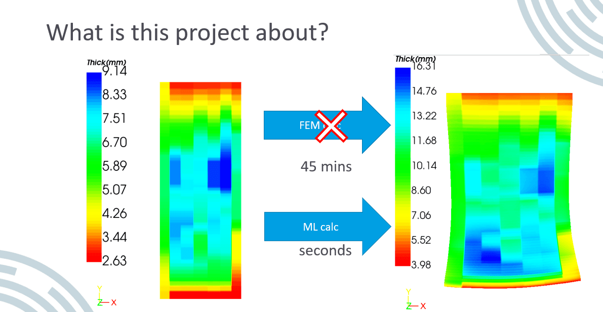
The whole argument in one figure: the same wall-thickness field, produced by the finite-element solver in about 45 minutes and by the trained model in seconds.
Scroll the figure sideways →
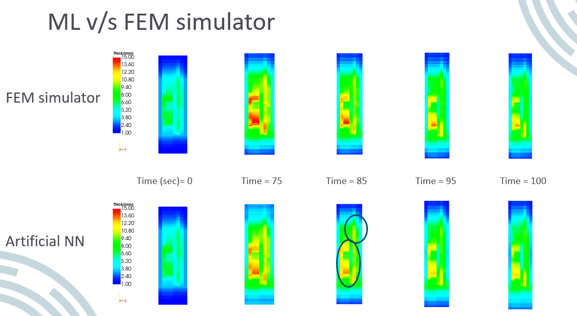
The surrogate against the solver, frame by frame through the moulding sequence. The circled regions on the lower row are where the network and the simulator disagree — kept in the figure deliberately, because a surrogate whose error you cannot point to is one you cannot deploy.
Scroll the figure sideways →
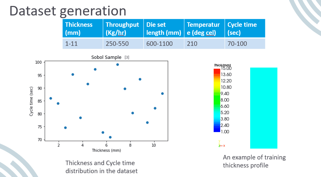
Where the training data comes from. The expensive solver is run offline across sampled configurations once, to buy a dataset — instead of being run online, per query, forever.
Scroll the figure sideways →
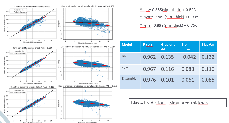
Error across the evaluated configurations — reported as measured, including the cases the model handles worst.
Scroll the figure sideways →
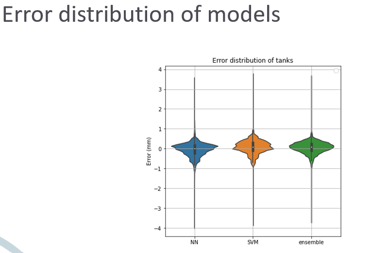
The distribution behind that error. The shape of the tail is what decides whether a surrogate is safe to put inside an optimisation loop — a good average with a long tail is still a trap.
Scroll the figure sideways →
How it was built
- 01
Generate the training set from the solver
The FEM simulator is treated as the ground-truth oracle: parameter sets are sampled, simulated, and the resulting thickness fields stored. The expensive step happens once, offline, to buy a dataset — rather than once per query, online, forever.
- 02
Learn the thickness field, not a single number
The network predicts thickness across the whole part at each timestep of the moulding sequence, so the output is directly comparable with the simulator frame by frame. That comparability is the point: a surrogate you cannot lay side by side with the solver is a surrogate you cannot trust.
- 03
Publish the disagreement
The comparison figure marks the regions where the network departs from the FEM result rather than cropping them out. A surrogate is only useful if its failure modes are known, because the one thing worse than a slow answer is a fast answer that is quietly wrong in the region you care about.
What this builds on
- Applied R&D project
- Built as a surrogate for an existing finite-element blow-moulding simulation. The timing contrast — a 45-minute solver run against a sub-second model evaluation — is the figure reproduced on this page.
Archive: add_pictures/blow mold